Analysis by Tom Palshaw
Note: The views and opinions in this report are solely those of the author and do not reflect those of any organization or person. The data used was publicly available from TIGHAR publications, related reports and blogs. DC-3 data is provided here so that the reader can review the data and make up their own mind. While I am supportive of TIGHAR's theory that Earhart landed on Gardner Island, I do not believe 2-2-V-1 came from a Lockheed 10.
INTRODUCTION
I became involved with artifact 2-2-V-1 back in 1992 when I mapped the rivet pattern in the belly of the New England Air Museum's Lockheed 10. Over the years the artifact has been subjected to many scientific tests and speculation as to its source. This discussion continues to this day. TIGHAR's operating theory was that if the artifact did not come from any other contemporary aircraft it must have come from Amelia's aircraft. I will present data that supports the idea that the artifact matches the right wing upper skin of a DC-3 of a certain serial number range.
ARTIFACT 2-2-V-1 / C-47B WING CHARACTERISTICS
These questions can be divided into two categories:
1. Deliberate characteristics (original design features) and
2. Consequential characteristics caused by events during the life of the artifact.
Deliberate characteristics include skin thickness, material composition, and structural attachment. They also include rivet type, size, pitch, and location. If any of these characteristics differ between the artifact and the wing then it can be said that the wing is not the source of the artifact.
Consequential characteristics are caused by events experienced by the artifact over time. It cannot be assumed that all features occurred at the same time. Artifact 2-2-V-1 shows clear evidence of a violent crash. It also shows signs of post crash cutting and repetitive fatigue bending fractures. While these features help to define the artifact, they might not eliminate the C-47B wing as its source as described here later.
DELIBERATE CHARACTERISTICS
The similarities between the artifact and the wings of a DC-3 were first noticed while restoring New England Air Museum's DC-3 (C-49J) s/n 6314, AAF# 43-1973, registration NC-55792 that was built in 1942. While much of the data matched, the skin edge near the -5 rivets was in the wrong orientation.
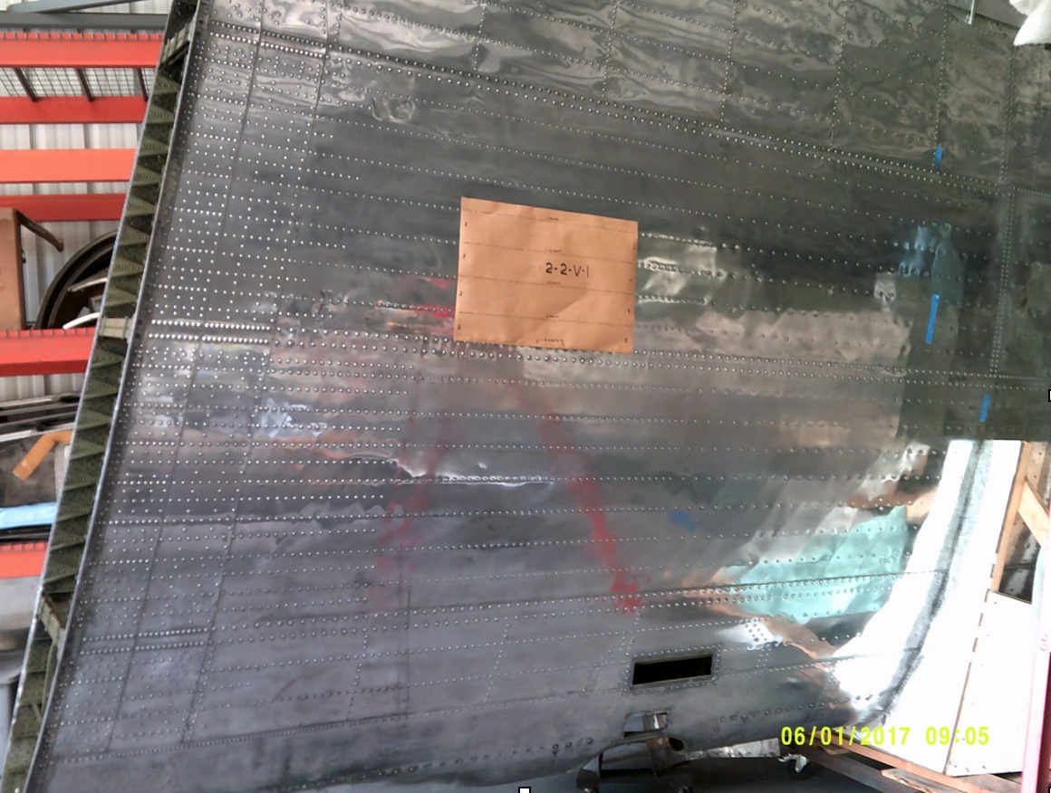
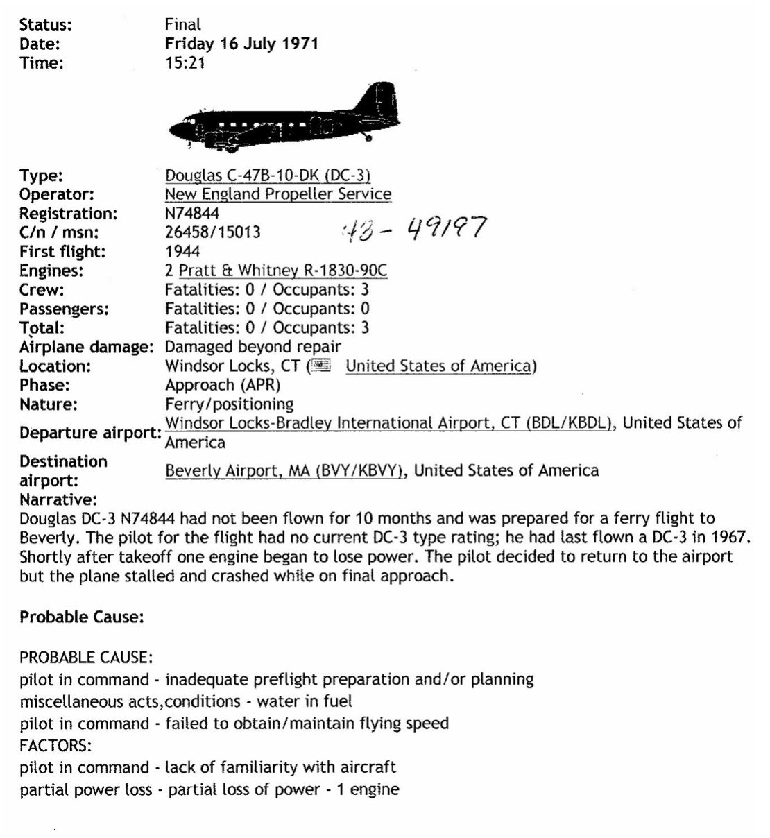
The museum also owns a spare wing in storage from a C-47B-DK, s/n 15013, AAF# 43-49197, registration N74844. This aircraft crashed at Bradley Field, CT on July 16, 1971; see Appendix I. A paper template of artifact 2-2-v-1, minus the tab, was made utilizing dimensions published in TIGHAR TRACKS , April 30, 1992, vol 8 #3. See photo below.
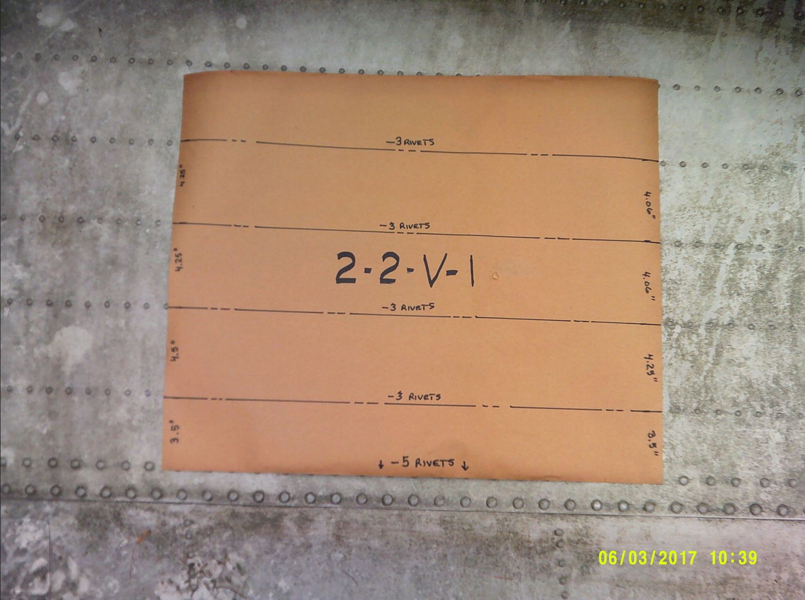 The 2-2-V-1 Template Laid Over the NEAM C-47B Wing. Source: Tom Palshaw
MATCHING CHARACTERISTICS
TIGHAR visited the New England Air Museum on July 16, 2017 with artifact 2-2-v-1 to inspect the wing in storage. The inspection was video taped but TIGHAR has not released that tape to the public. Several questions were raised during the inspection that required further inspection. That additional inspection was conducted on July 18, 2017. The results were emailed to TIGHAR. See Appendix II for information about measurement methods.
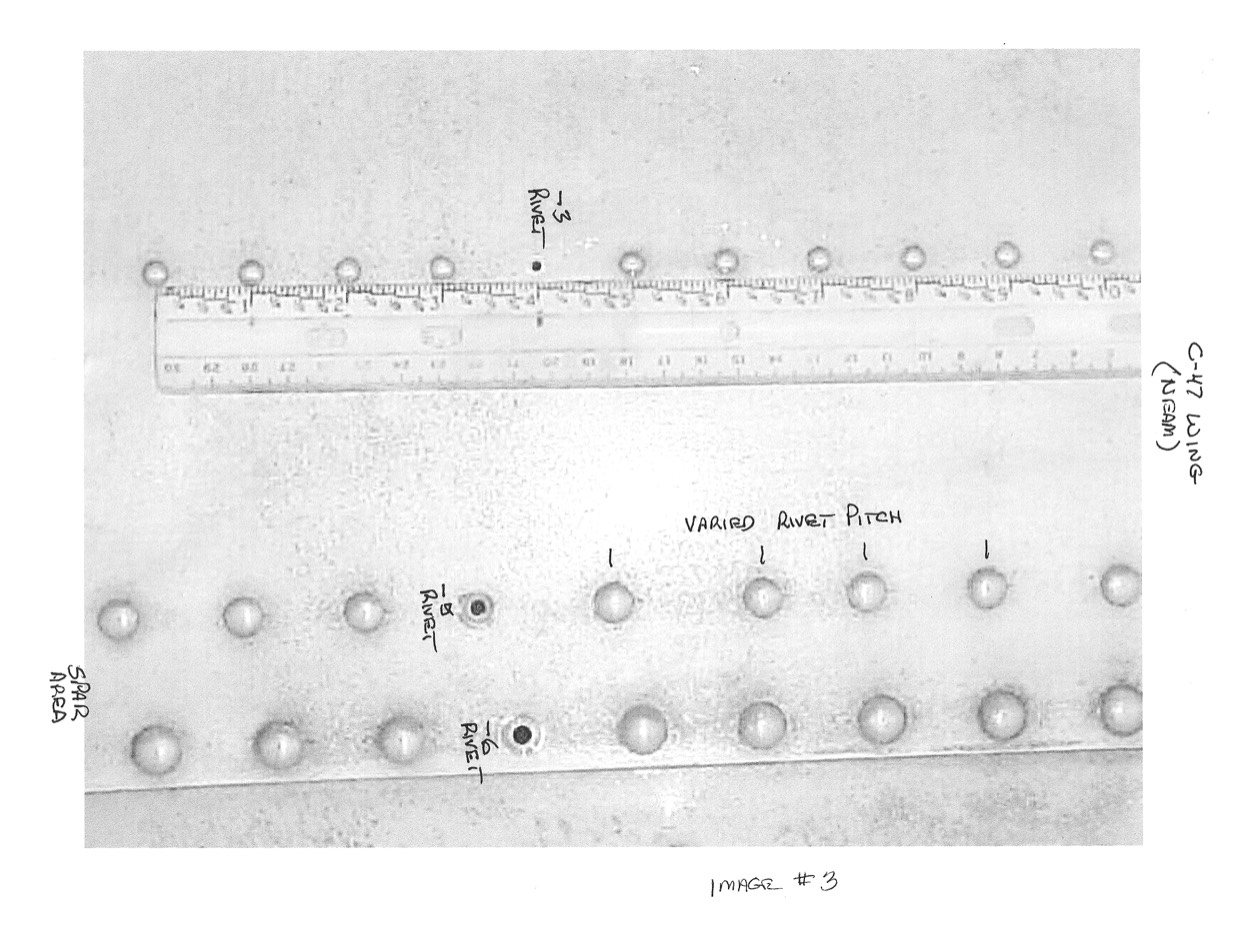
Rivet size: The size of the rivets in the area of interest on the C-47B wing was questioned. During the follow-up investigation one rivet was removed from the wing in this area on Tuesday, 7-18-17. This confirmed the rivets in question were -3 brazier head rivets. These match the known rivet size and length of the artifact. (Side note: The rivets on the C-49J wing, constructed 1942, are also -3 rivets.) The thickness of the underlying stringer was measured and found to be 0.060" thick.
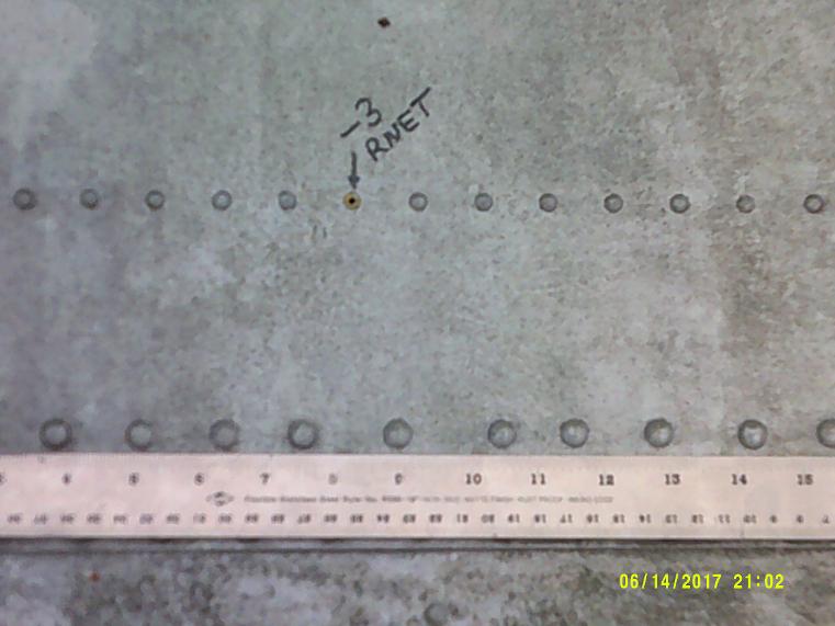
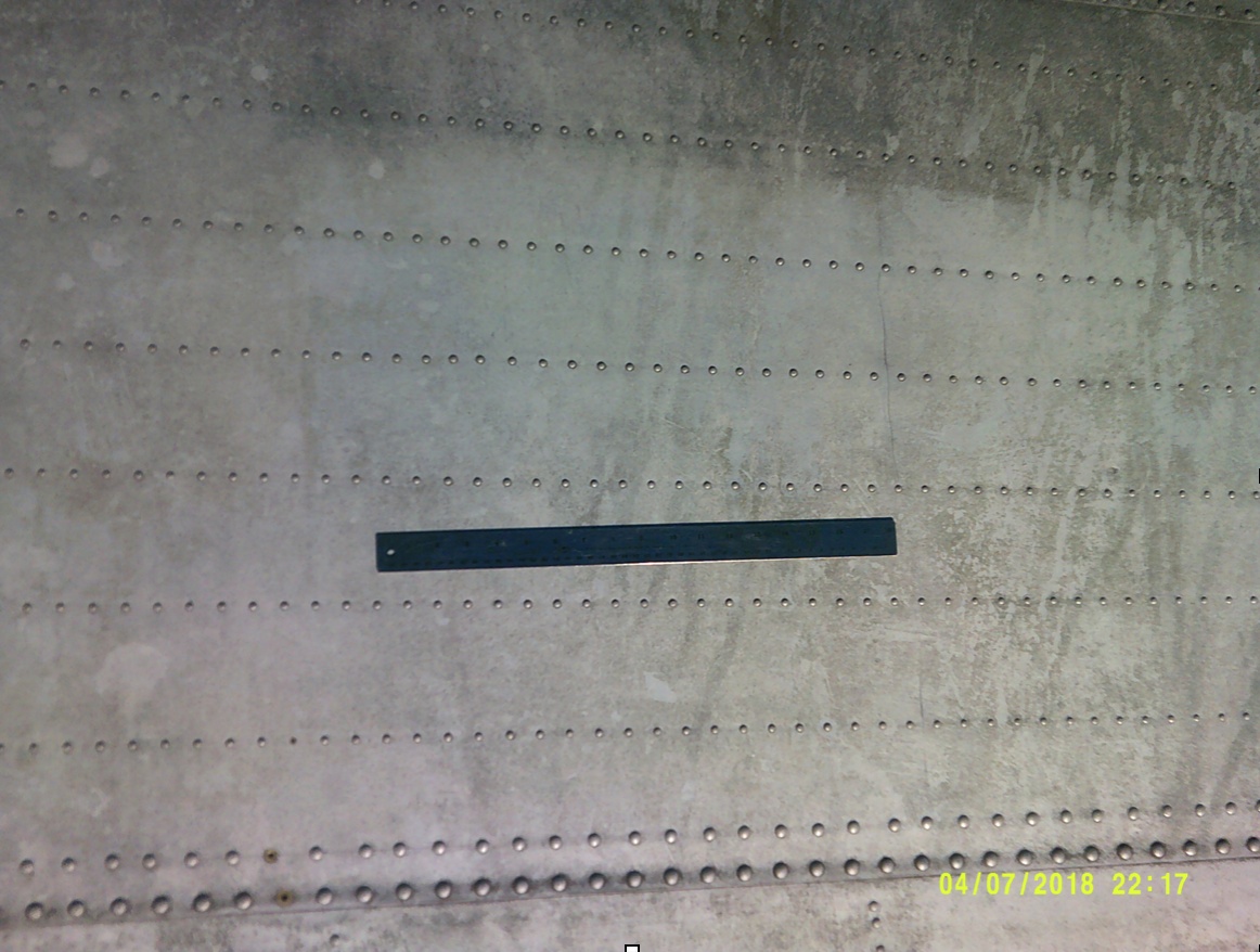
Rivet pitch variation of the -5 rivets: Artifact 2-2-V-1 has rivet pitch variations of the -5 rivets. It was initially assumed that C-47B wing rear spar** rivets had a constant pitch of 1.25”. When re-examined on 7-18-17, it was found that the wing rivet pitch varied randomly from 1 3/16 to 1 9/16 inches; see photo below. There was no obvious reason for these variations. This new information should be compared with the data from the Artifact 2-2-V-1.
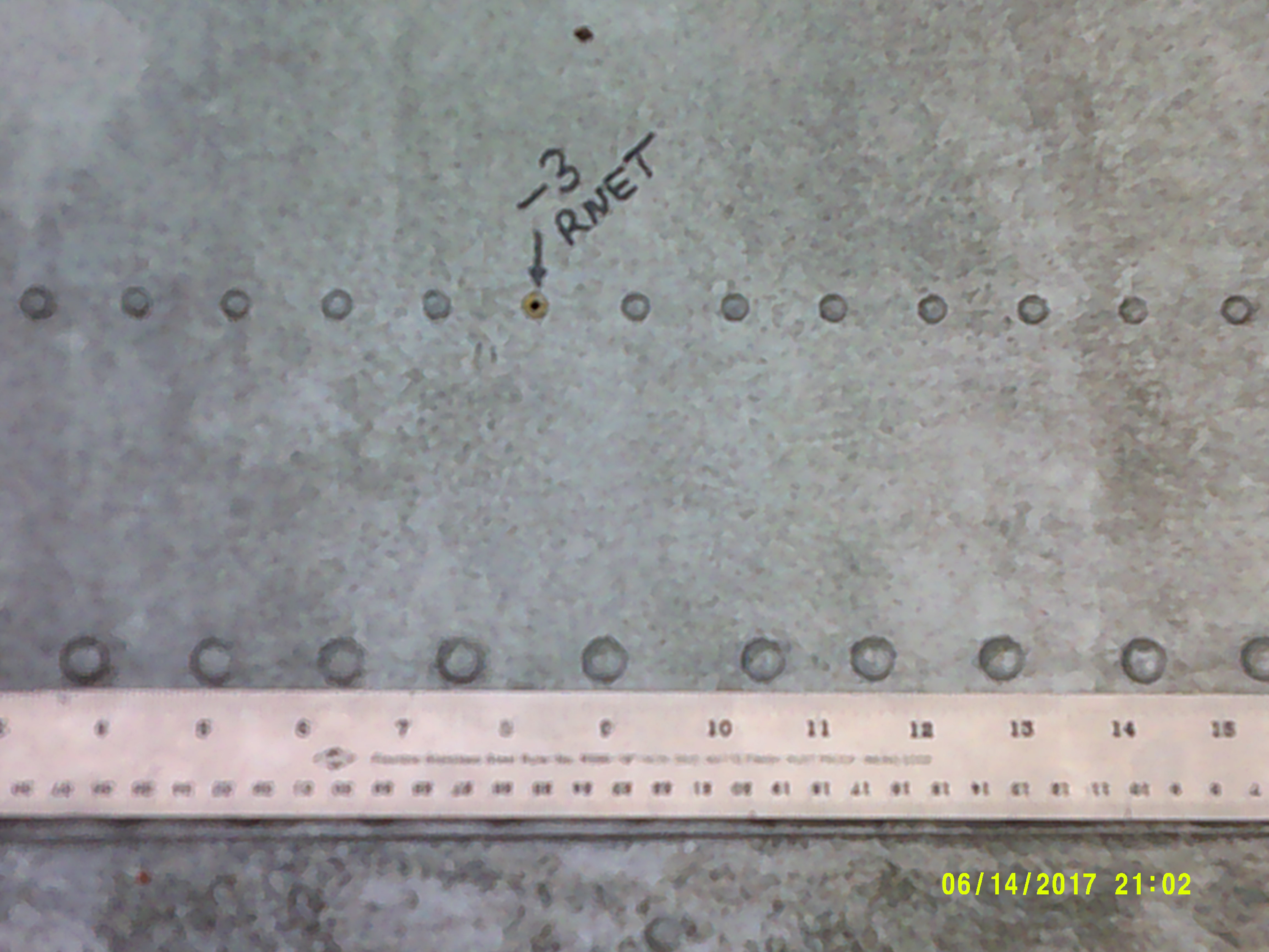 Irregular Spacing of -5 Rivets on C-47B Wing. Source: Tom Palshaw
WHAT ON ARTIFACT 2-2-V-1 MATCHES THE WING OF A C-47B?
- The artifact and the wing skin are 0.032" thick Alclad aluminum.
- The -3 brazier head rivets have 1" pitch and 0.060" underlying stringers.
- The stringer alignment matches the data published in TIGHAR TRACKS.
- The -5 brazier head rivets match the varying pitch of the tab and the rear spar** of the wing. The spacing between the rows of the -5 rivets matches the rear spar** of the wing.
- The artifact rows of -5 rivets do not match the lower frame of the Lockheed 10 window. The Lockheed 10 rivets were smaller and more closely spaced; see photo below. This indicates that the artifact did not come from Amelia's airplane.
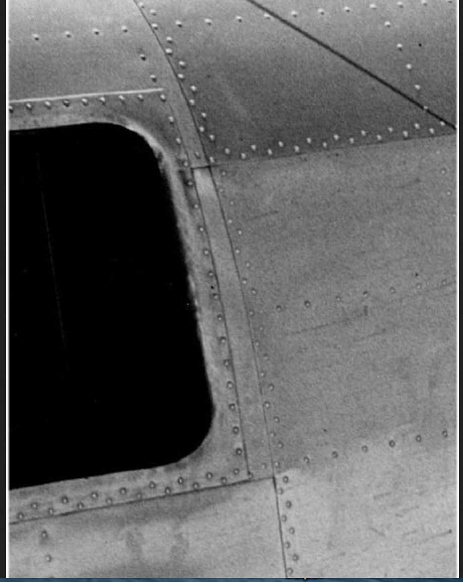 Lockheed 10 Window Frame. Source: TIGHAR
- The s/n of the Sydney Island crash (13890, 1943 ) and the Bradley crash (15013, 1944 ) are reasonably close.
- The only surviving component from the crash on Sydney Island was the right wing, which broke off when it hit a tree, C-47A, s/n 13890, AAF# 43-30739.
- The Gilbertese settlers were known to travel to Sydney Island and salvage material from crashed aircraft.
- The chemical composition of the artifact matches World War Two aluminum, not 1930's aluminum; see table below.
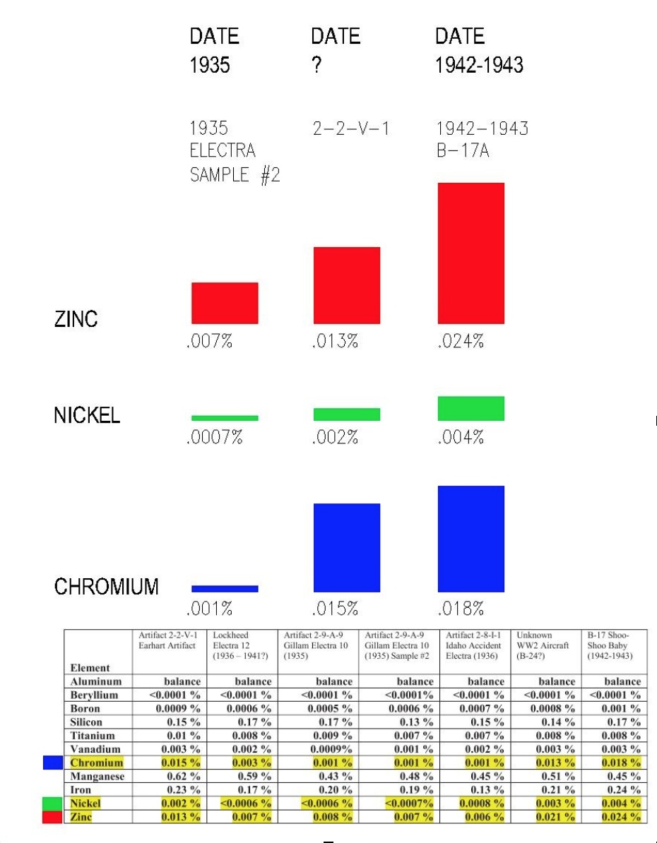
Lehigh Testing Lab Chemical Analysis Data, Job # R-48-20 Dated Jan 6, 2015. Source: TIGHAR
CONSEQUENTIAL CHARACTERISTICS
It was assumed that the fatigue failure on artifact 2-2-V-1 was caused by back and forth bending of the artifact while still attached to the source aircraft. This cannot be proven. The bending could have occurred later. The fatigue failure lines are so straight as to have another possible meaning. If the artifact had been wrenched from an attached underlying structure the fracture line should have been more uneven based upon the variance of stress at and between attaching fasteners. It is quite possible that artifact 2-2-V-1 was originally larger when removed from the source aircraft. A piece could then have been removed later by placing the artifact between two straight angles and flexed to failure by locals to make handicrafts. This would better explain why the fatigue fracture is absolutely straight.
** - Note: As originally published, this report mistakenly referred to the center spar of the NEAM C-47B wing as the location of a line of -5 rivets that corresponds to a line of -5 rivets on 2-2-V-1. The rear spar is the correct location of that rivet line, as the report now states.
-----
UPDATE FEBRUARY 5, 2020: EVALUATING THE THICKNESS of 2-2-V-1 and the C-47 WING SKIN
Note: The views presented here are strictly the views of the author. The New England Air Museum is a 501c3 educational organization and does not hold a position on this research. They have provided their artifacts for research to benefit the public's interest in the topic. I thank them for their cooperation.
HISTORIC RESEARCH
When researching historic events one starts with observed data, forms an opinion, and then researches deeper to validate the data. The data is then submitted for peer review and questioning.
2-2-V-1 AND THE C-47B WING
The investigation of Artifact 2-2-V-1 raised some detailed questions regarding a match to the upper skin on the right wing of a C-47B constructed in 1944.
These questions can be divided into two categories; 1. Deliberate characteristics (original design features) and 2. Consequential characteristics caused by events during the life of the artifact.
Deliberate characteristics include skin thickness, material composition, and structural attachment. They also include rivet type, size, pitch, and location. If any of these characteristics differ between the artifact and the wing then it can be said that the wing is not the source of the artifact.
Consequential characteristics are caused by events experienced by the artifact over time. It cannot be assumed that all features occurred at the same time. Artifact 2-2-V-1 shows clear evidence of a violent crash. It also shows signs of post crash cutting and repetitive fatigue bending fractures. While these features help to define the artifact, they might not eliminate a C-47 wing as its source as described here later.
Earlier discussions involved rivets, patterns, and materials. This update is centered on DC-3/C-47skin thickness, and whether it is a match to artifact 2-2-V-1.
SKIN THICKNESS
Aluminum sheet is identified by its "nominal" thickness. Our discussion is about 028 and 032 ALCLAD (0.028" and 0.032" respectively). This is the number used when ordering, designing, or repairing a structure. It is a deliberate characteristic.
Manufacturing aluminum sheet is made with a production tolerance. This is limited by an industry or government specification. QQ-A-335 dated December 7, 1939, Federal Specification for Aluminum-Alloy (AL-24) is an example. The production tolerance for the thickness and width of our research is + or - 0.0025". This means that 028 can be 0.0255" to 0.0305" and 032 can be 0.0295" to 0.0345".
It is important to use the production tolerance standard appropriate to the artifact. The modern production tolerance for the same thicknesses today is + or - 0.0015".
MEASURING THE THICKNESS OF ALUMINUM SHEET
Measuring the thickness of a new sheet of ALCLAD is as simple as using a standard 1" micrometer. The metal is smooth, flat, and clean. Once the metal has been installed, or exposed to the elements, several factors can affect the accuracy of the measurement. These include a paint coating, corrosion, shape, installed fastener effects and stress induced changes to its original dimensions.
The lack of access to both sides of the sheet would require measuring the step at the edge of the sheet. This can be done with a depth gage or dial indicator. Modern techniques such as eddy current and ultrasonic micrometers can be used when only one side is available. (see appendix for a description of ultrasonic measurement)
THE DC-3 AND C-47B WINGS
The original measurement done at the New England Air Museum was done on the DC-3 wing. The wing was in a cradle so the inboard edge of the wing skin was available. The "nominal" thickness was found to be 0.032". The wing has since been installed so the original measurement cannot be repeated.
The C-47B wing is a spare cut inboard of the center section flange of an accident aircraft. The aft edge step of the skin was first measured with a depth micrometer. This was repeated later using a dial indicator. Both measurements exceeded 0.032". This created a dilemma as both the DC-3 and the C-47 structural repair manuals list this skin to be 028 (nominal).
ULTRASONIC THICKNESS MEASUREMENT RESULTS
The Bombardier Business Aircraft Service Center, located in Windsor Locks CT, provided a level 2 NDT technician to perform ultrasonic thickness measurements on the DC-3 and C-47B wings. The equipment used was a calibrated Olympus 38DL PLUS Ultrasonic Thickness Gage utilizing an M116-RM, 20MHz, transducer, p/n U8400039. Both aircraft right wings were inspected by selecting five locations between the -3 rivet lines in the area of interest.
C-47B, s/n 15013, 43-49197, N74844, Manufactured 1944
Skin condition: Unpainted alclad but weathered from 50+ year's exposure to the elements. The surface was cleaned with a Scotchbrite pad to a smooth finish.
Thickness measurements: 0.032", 0.031", 0.032", 0.031", 0.032"
DC-3, s/n 6314, 43-1973, NC-55792, Manufactured 1942
Skin condition: Clean, smooth, polished Alclad.
Thickness measurements: 0.027", 0.030", 0.030", 0.027", 0.028"
ARTIFACT 2-2-V-1
The artifact has been identified as 032 Alclad by several testing labs. It is assumed that this is the "nominal" thickness, as no actual thickness measurements have been published. Consequential effects listed above would also apply to measurements on 2-2-V-1. The edge marked "Failure #1" would have to pass through the elastic yield limit (41kpsi) before finally failing at its ultimate limit (52kpsi), possibly changing the thickness. The metal would have stretched before it failed. (Elongation minimum in 2 inches = 10%, ref QQ-A-355). The edge marked "Failure #2", the hacked edge, did not experience the same stresses, and would have retained its original thickness. A more detailed investigation of the artifact's thickness variation would be needed to determine if stress had this effect.
CONCLUSIONS
Given the results of both the mechanical and ultrasonic thickness measurements of the C-47 wing indicating a skin thickness of 032 ALCLAD we are left with two questions to answer:
1. Do other C-47 wings have the same result regardless of the structural repair manual data?
2. Does engineering data approval exist that permits the installation of 032 skins? Possibly engineering changes to Douglas Drawing 5115200.
---
October 2020 Update:
Is the Damage to 2-2-v-1 Consistent with the Damage to the C-47 Wing on Sidney Island?
If 2-2-v-1 came from the Sidney Island C-47 crash then two criteria must be met:
Does 2-2-v-1 match the skin pattern of a C-47 wing? Previous research indicates that it does.
Is the damage to 2-2-v-1 consistent with the damage to the C-47 wing on Sidney Island? The following analysis proposes that it could.
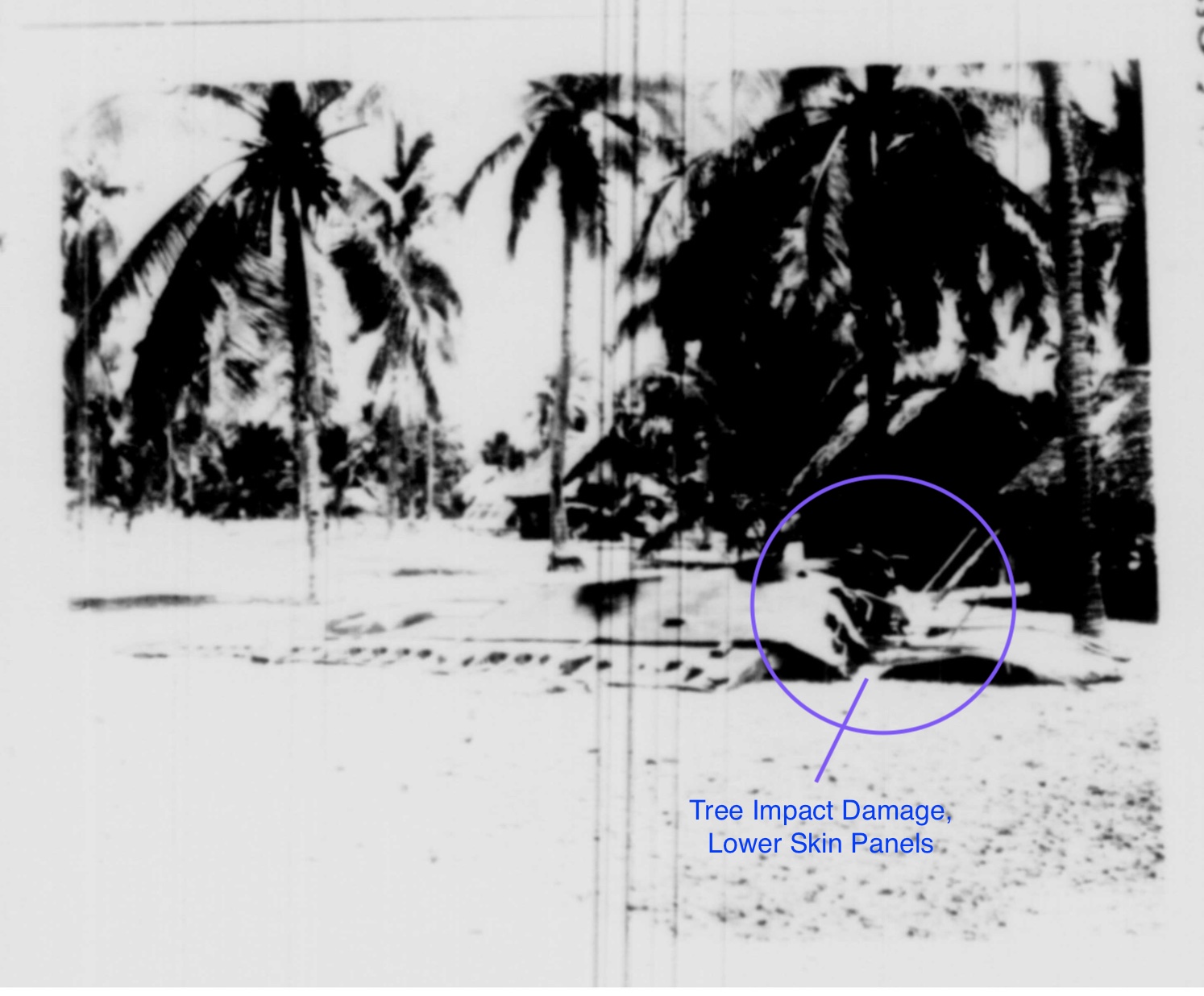
1. A photo of the Sidney Island wing from a 1943 Army Air Force accident report shows that the tree impacted the right wing just outboard of the engine nacelle near wing station 35.8. Loose panels of skin can be seen hanging from the fracture zone (note: wing is lying upside down in this photo). This is consistent with the area of interest on the NEAM wing, as indicated in the analysis image #1 beneath the photo.
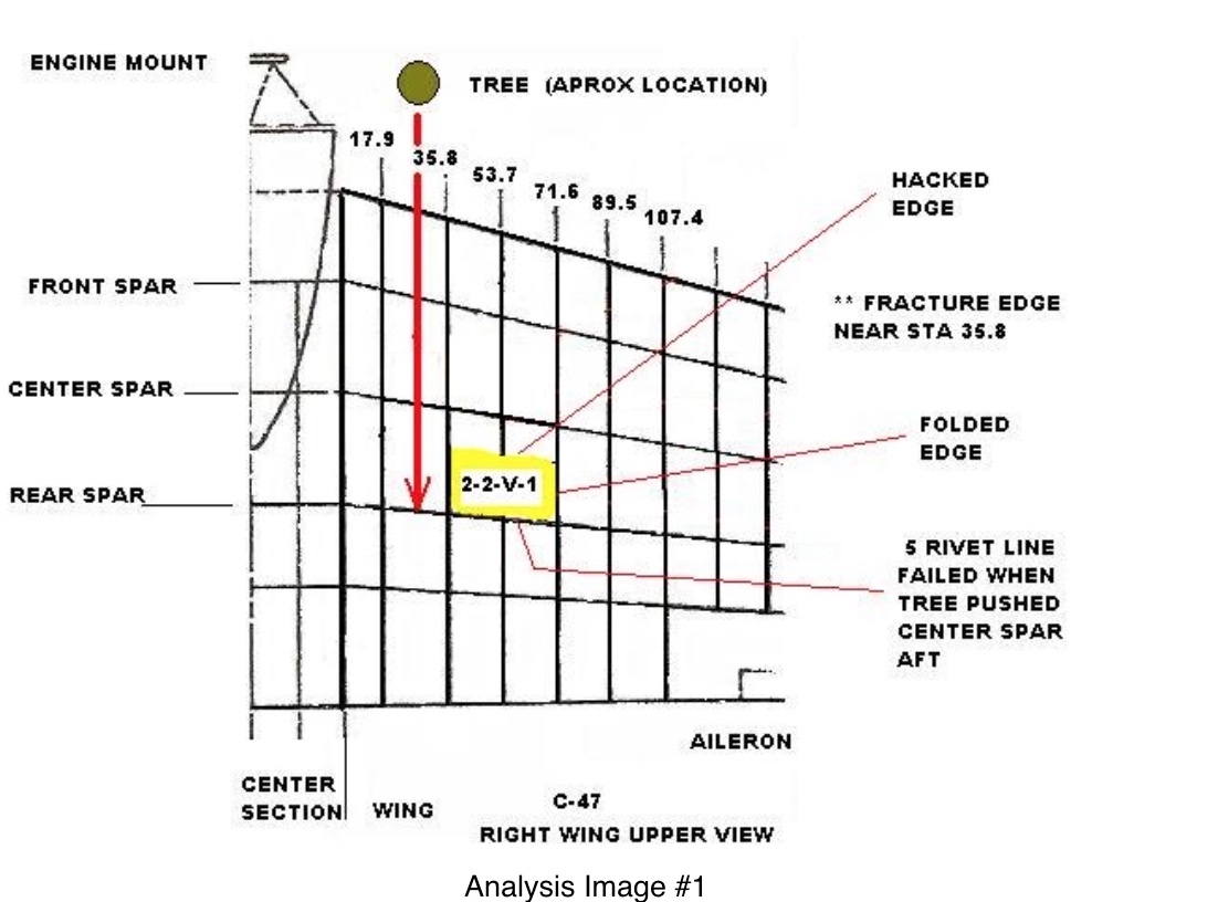
2. See analysis image #2 below; all fracture numbers were provided by TIGHAR. Fracture #2 could have been caused when the tree cut through the wing. Fracture #1 could have been caused when the tree impacted the spar, pushing it aft. The -5 and -6 rivet lines failed when the spar, being stronger than the skin, moved aft.
3. See analysis image #2 below; failure #3 was in part caused by the crash and in part caused by fatigue bending when the panel was salvaged by local people. The hacked edge was also caused when the panel was salvaged from a larger piece.
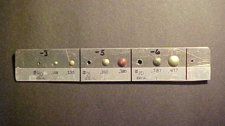
4. Image #3 below shows the -3, -5, and -6 rivet lines of a C-47 wing.
A. The -3 rivets match artifact 2-2-v-1.
B. The -5 rivets match the varied pitch of the -5 rivets in 2-2-v-1.
C. The -6 rivets are consistent with the larger partial hole in 2-2-v-1.
Conclusion
While this analysis does not prove that 2-2-v-1 came from the Sidney Island crash, it does show that it is possible. The Sidney Island crash cannot be ruled out.
CONTACT
Questions and comments can be sent to the author at:
![]()
REFERENCES
Original Report
TIGHAR TRACKS, April 30, 1992, vol 8 #3, page 5.
NTSB Report # 92-40, Mar 5,1992, DCA 37-I-A001, July 5, 1937
‘The Crash at Sydney Island’ TIGHAR Project Report #7, 7/26/98
Lehigh Testing Lab, Job # R-48-20 Dated Jan 6, 2015
Air Safety Network accident reports (Flight Safety Foundation)
February 5 Update
1. NTSB Report 92-40, Mar 5, 1992
2. MMR Report 128927, Aug 27, 2019
3. ASTM B209-96
4. TIGHAR Tracks, vol35 #3, Oct 2019
5. Federal Standard QQ-A-355, Dec 7, 1939
6. Olympic Industrial Resources, Tom Nelligan (extract)
October 2020 Update
The Sydney C-47 wing photo is from an Army Air Force Accident report dated 17 December 1943, accident number 44-12-17-507.
See the Ghost of Gardner Island blog for additional information not covered above.
---
APPENDIX I: C-47 ACCIDENT REPORT
APPENDIX II: MEASUREMENT METHODS
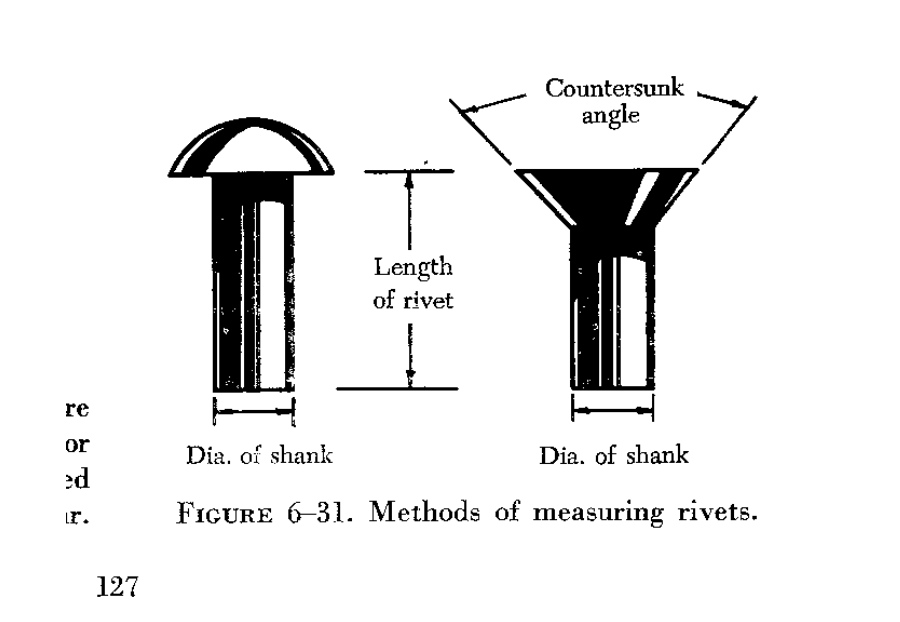
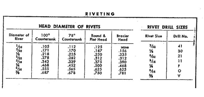
Let me start by making a blanket statement: All rivets are identified by the size of the shank, not by the size of the head.
To identify installed rivets in any structure would require determining both the shank diameter and the grip length. Rivet diameter is in 1/32", grip length is in 1/16". A -4 rivet is 4/32" in diameter. Reference FAA Mechanics General Handbook AC-65-9(1970), Chapter 6, page 127, figure 6-31 shown below.